Spring is knocking at the door, and I am not ready! I have several projects already lined up that I want to use this tractor for, so I need to get it finished up! That said, I still want to paint it since it is disassembled and it is a new skill I want to learn.
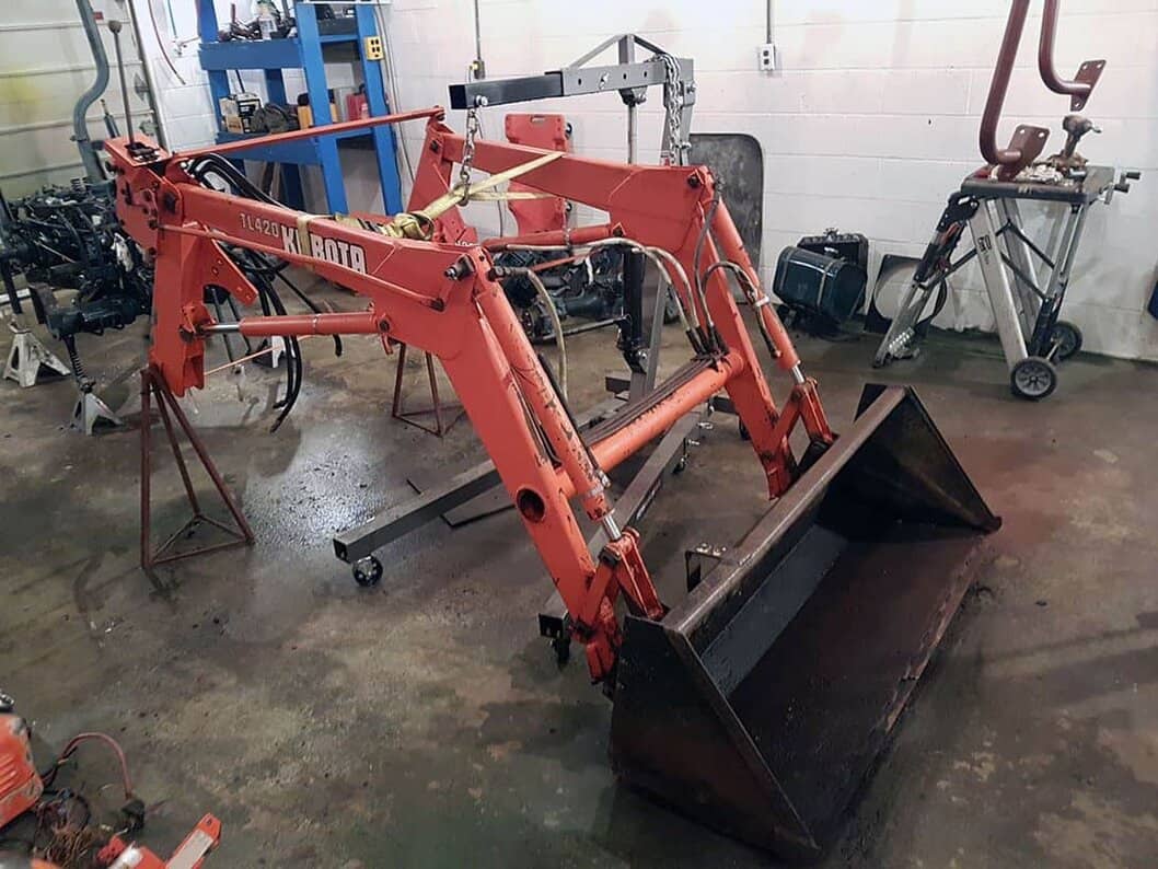
I separated all the orange bits from the blue bits, so I could cut down on much of the masking and do a better job at the transitions. I had to figure out a way to lift the loader off without being able to use its own hydraulics (which is how they always seem to be removed on YouTube). I put it in a sling with a ratchet strap and lifted with my engine hoist. I put the rear tires back on the tractor, a rolling hydraulic jack under the front, and rolled the chassis out from under it.
Sidenote – I am not sure why I always end up doing these things in the least efficient order! If I had just removed the loader in the very beginning 1) the tractor would still had both axles and rolled out from under it much easier and 2) removing the front axle / engine would have been so much smoother not working around the loader arms.
Then I welded up some scrap steel to support it using the wedge bolt pin holes. I had to add a strap to keep my support pins from wanting to walk out when working on it, and another to keep the main arm cylinder from wanting to expand & tipping my support stands over.
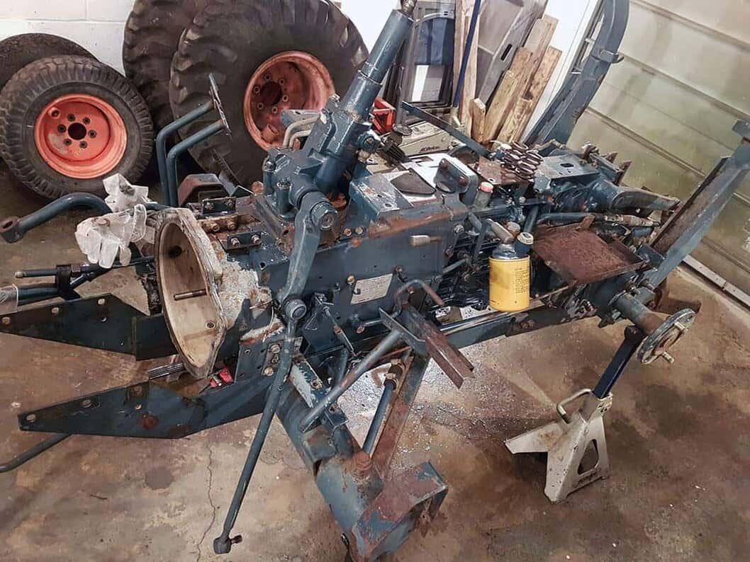
These machines have a lot going on under those fenders!
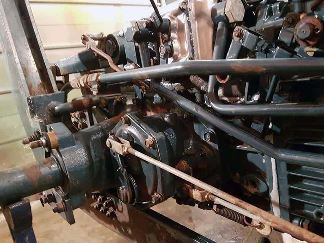
Now I am sanding out as many of the blemishes as I can. I have some new decals on order, and hopefully will soon be laying down some nice shiny new paint.
It’s been several weeks since the last update, and I really was hoping the next update would be a running engine. Unfortunately I had a setback on that, which I will get into shortly. This one is going to be a double update!
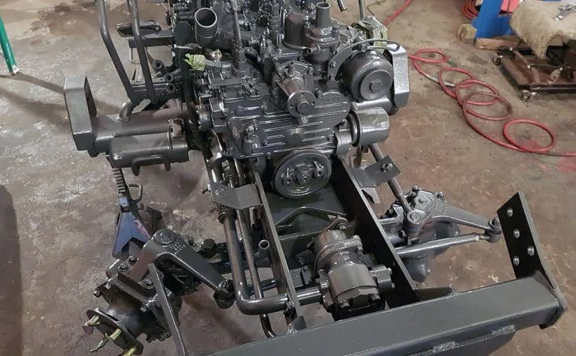
First up is that the engine and chassis painted up very nicely. I painted the engine and each of the disassembled chassis sections separately, and then again after having them re-assembled. This allowed me to get better coverage on each section, and then the additional coats after assembly took care of the scratches from re-assembly that are bound to happen.
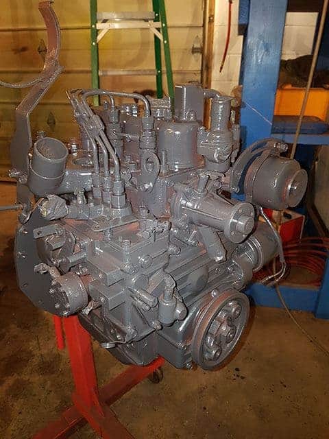
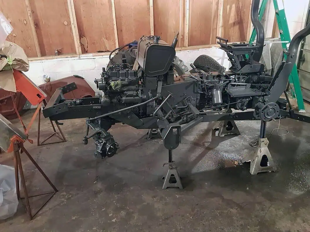
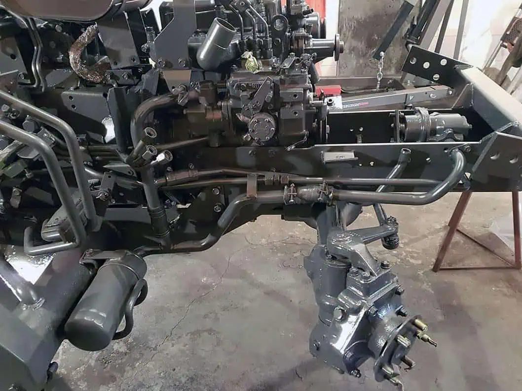
The cherry picker / hydraulic shop crane has proven invaluable for this project. Besides the normal engine pulling / installation, I have been able to use heavy ratchet straps to sling larger assembly’s like the entire front end loader and the front axle / chassis sub-frame. With careful control of each ratchet strap, I was able to pitch the assembly just how I needed and then line up the frame bolt holes for assembly completely by myself. Even with the aid of several big guys, I do not think that could have been done very easily without it!
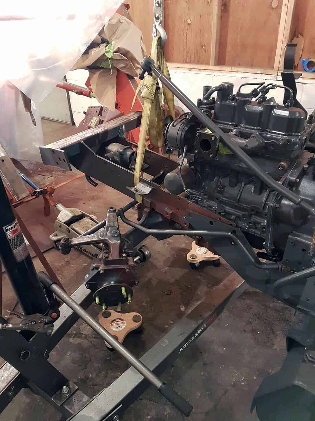
Once the engine and chassis were all bolted back up, I wanted to test fire the engine before assembling it any further.
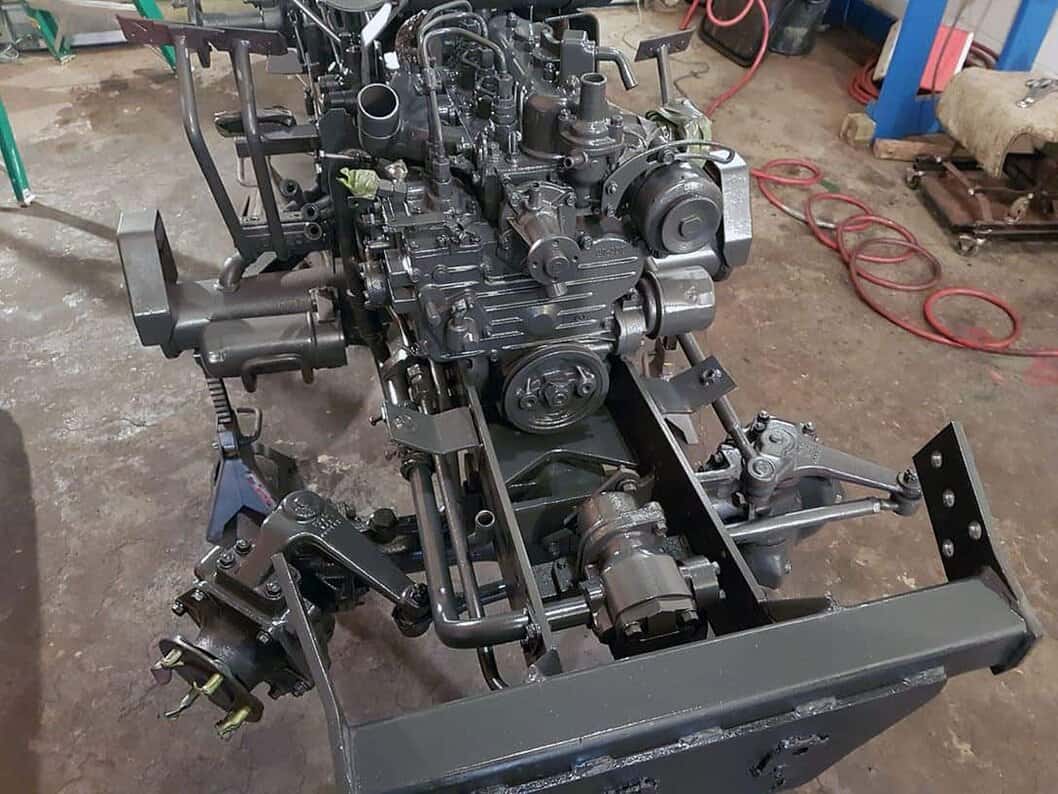
I hooked up the minimum connections needed in order to get fuel to the injection pump, and power to the glow plugs and starter. I did not have the radiator installed yet, so I would only be able to run the engine briefly. I also had a scrap piece of wood handy to suffocate the intake with, just in case I did not get all the governor springs inside the injection pump reinstalled correctly.
I bled the air out of each of the injection lines, energized the glow plugs, and cranked it over. Sadly it wouldn’t start. I gave it several attempts and re-bled the injector lines just in case they still had too much air. Eventually I gave up for that night. Later I took the injectors back out for a compression test. I was seeing compression of about 200 psi on #1 and #3, and only 90 psi for cylinder #2. I double checked the valves were adjusted correctly, as that can also give low compression, but all was good there.
I began to suspect the head was cracked from overheating. I know the engine had a history of overheating before it was taken out of service 9 years ago, and likely ran without coolant on at least one occasion due to the cracked T-stat housing I found.
When I had it apart, the cylinder head was warped (about 8 thousands out). I was able to re-surface it myself following YouTube videos, and brought back to within 2 thousands of being flat, which is the workshop manual spec. I also lapped the valves, and was not able to visually see any cracks at that time.
It did not really make sense to have it sent into a shop to be magnafluxed, as the #2 cylinder was pretty eroded, and these heads are cheap enough that if it was cracked a new head from eBay would likely be the same cost or less than repair work on the head. Given that, and the eroded #2 head area, it would not make sense to spend a lot of money repairing this head. But since I didn’t see any cracks at the time, I was willing to invest in a head gasket to give it a shot.
Later after it was all assembled and I had painted the engine, I noticed a crack on the external surface of the head. It appeared to be only in the water jacket area, so I put epoxy on it and tried to forget it was there to ease my mind! But now that my compression is low, the most obvious answer is there were additional cracks that I had not seen.
The good news is I was able to pull the head fairly quickly, without needing to remove the entire engine again.

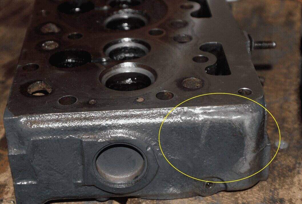
I stripped the old head and cleaned it back up for a second inspection. I used a brighter light and a magnifying glass this time. I did find there are at least two cracks in the combustion area, between the valve seats and web to the recessed combustion chamber. Here is a full shot of the head, and even knowing where to look in the photo, I can’t see the cracks. You can see the large pitting / erosion of the #2 cylinder though, which is why I didn’t want to invest in any machine shop work for this head.

Here is where I epoxied the external crack I had mentioned in the previous post.
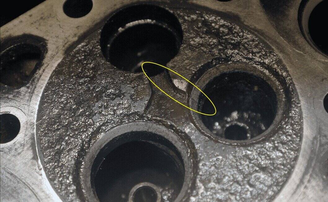
This is the first internal crack I found. It runs well into the valve recess, across the hardened valve seat, along the lower corner of the valley and down into the recessed combustion chamber. This one actually shows a little better in the photo than it does in person. The camera flash must catch it well.
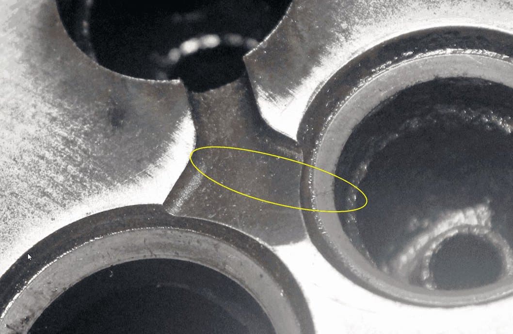
I also discovered this one as well. It crosses the valve seat, and then continues straight into the valley between the ports. It’s harder to see, but its there.
I have purchased some penetrating dye and developer to make finding these kinds of issues at home much easier in the future. I may test it out on this scrap head when it comes in just to see what else shows up!
In the mean time I have ordered a Kumar Bros aftermarket replacement head for this engine. The reviews I could find were mostly positive, and it is quite a bit less expensive than a genuine Kubota one. Hopefully the next update will be a running engine!
Click here for Part 7 on the Kubota B20 rebuild.

how did you get the engine and hydraulic pump shaft aligned? We have messed up 2 sets of disks and are about at our wits end.
I have a B20 Kubota. It had backhoe, but I removed the backhoe. But the the tree point lift is not working. What can be wrong ?? I need to use the tractor for garden. Not having the tree point working I cannot use it. Thank you